Tiếng Việt
User manual
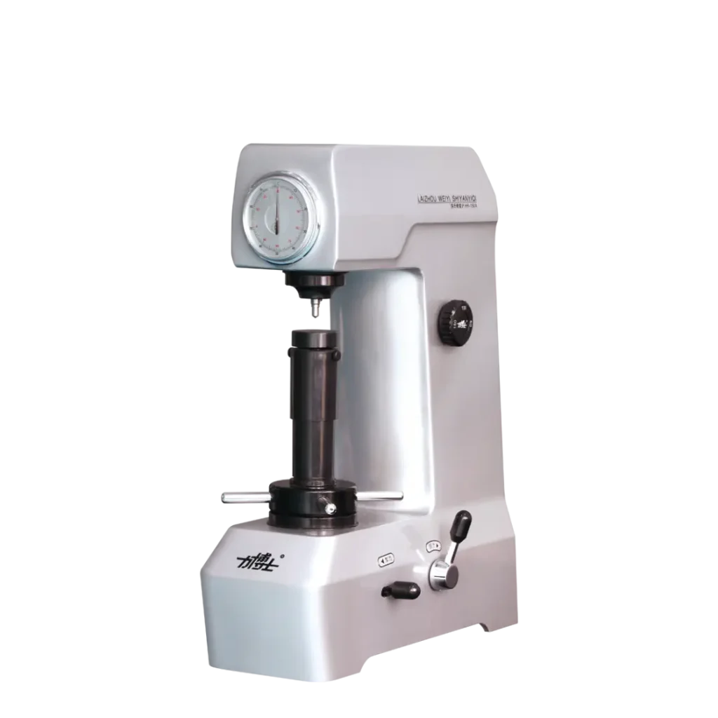
Comprehensive Guide to Operating the HR-150A Manual Rockwell Hardness Tester
11
Jun
Jun
Comprehensive Guide to Operating the HR-150A Manual Rockwell Hardness Tester
The Rockwell hardness tester HR-150A is a classic, purely mechanical instrument widely utilized in machine shops, heat treatment facilities, and quality control laboratories. Because this tester operates completely manually without any electrical components, understanding the exact technical procedure is critical. Proper operation ensures precise test data, protects the expensive diamond indenter from chipping, and prevents damage to your test specimens.
This comprehensive guide delivers a step-by-step technical walkthrough to operate the HR-150A Rockwell hardness tester safely, accurately, and in full compliance with international testing standards.
1. Pre-Operation Setup and Material Selection
Achieving reliable results with a Rockwell hardness tester depends heavily on meticulous pre-test preparation. Any instability in the specimen or incorrect configuration will induce severe measurement errors.
Specimen Preparation Requirements
- Surface Quality: The test surface must be ground smooth, flat, and polished. It must be entirely free of oxide scale, rust, oil, grease, or surface lubricants.
- Thickness Limits: The specimen thickness must be at least 10 times the expected permanent depth of the indentation. If the back surface shows any signs of deformation after testing, the specimen is too thin.
- Stability: The bottom surface of the specimen must be perfectly flat and rest flush against the testing anvil. Any rocking, tilting, or flexing under load will yield false low hardness readings.
Choosing Indenters and Test Loads
Before starting, you must configure the Rockwell hardness tester according to the material scale required. The three primary scales are:
- HRC Scale (Hardened Steel, Tool Steels): Install the 120° Diamond Cone Indenter. Set the total test force to 150 kgf by turning the load selection knob at the back or side of the machine.
- HRB Scale (Soft Steels, Copper, Aluminum Alloys): Install the 1/16-inch (1.5875 mm) Steel Ball Indenter. Set the total test force to 100 kgf.
- HRA Scale (Carbides, Thin Hard Sheets): Install the 120° Diamond Cone Indenter. Set the total test force to 60 kgf.
2. Step-by-Step Operating Procedure for HR-150A
Once the indenter and test load match your material requirements, execute the following five-step mechanical testing sequence:
Step 1: Mounting the Specimen
- Place the prepared specimen securely onto the appropriate testing anvil. Use the large flat anvil for wide samples, the small flat anvil for small pieces, or the V-notch anvil for cylindrical shafts.
- Ensure the sample sits perfectly level and centered beneath the indenter axis.
Step 2: Applying the Preliminary Test Force (Preload of 10 kgf)
- Slowly rotate the elevating handwheel clockwise to raise the anvil, bringing the specimen surface into contact with the indenter tip.
- Continue turning the handwheel slowly and watch the dial gauge indicator. The small pointer will begin to move.
- Rotate until the small pointer aligns perfectly with the red dot (or setting mark).
- Simultaneously, the large pointer will complete exactly three revolutions. It must stop within ±5 divisions of the 0 position (the “C” mark) on the outer scale. This signifies that the minor load of 10 kgf is fully applied.
Step 3: Zeroing the Dial Gauge
- If the large pointer does not rest perfectly on the 0 mark, do not force the handwheel. Instead, gently rotate the outer bezel of the dial gauge housing until the “0” line (or “C” mark) aligns perfectly with the exact position of the large pointer.
Step 4: Applying the Total Test Force (Major Load)
- Smoothly push back the operating handle (typically located on the right side of the machine body) to release the major load mechanism.
- Watch the large pointer rotate backward as the major load is driven into the material.
- Once the large pointer comes to a complete stop—which indicates that the oil dashpot cushion has fully settled—allow the load to dwell for 4 to 8 seconds to achieve plastic deformation stability.
Step 5: Unloading and Reading Hardness Values
- Smoothly and steadily pull the operating handle forward to its original starting position. This action removes the major load while maintaining the 10 kgf minor load.
- Read the final hardness value directly from the dial scale intersected by the large pointer:
- For diamond indenters (HRC or HRA scales): Read the Black Scale (Outer Circle/C Scale).
- For steel ball indenters (HRB scale): Read the Red Scale (Inner Circle/B Scale).
- Turn the elevating handwheel counter-clockwise to lower the anvil, release the sample, and complete the testing cycle.
3. Critical Troubleshooting and Maintenance Tips
To prevent operational bias, mechanical failure, or expensive component damage, adhere strictly to these industrial guidelines:
- Mind the Spacing: Never test too close to an edge or an existing indentation. The distance between the centers of two consecutive indentations must be at least 3 times the diameter of the indentation.
- Discard the First Reading: Whenever you change the indenter, swap the anvil, or start a new shift, the first test indentation must be discarded. This initial test seats the mechanical joints and seating surfaces tightly into place.
- Protect the Diamond Tip: The diamond indenter used in a Rockwell hardness tester is highly sensitive to lateral impacts. Never allow a sample to slide horizontally against the tip while under pressure, and avoid hitting the tip with hard tools.
- Daily Verification: Always run a verification check using the certified standard hardness blocks provided with your machine before testing production parts. If the reading falls outside the tolerance indicated on the block, the machine requires calibration.
4. Conclusion
Operating the manual HR-150A Rockwell hardness tester requires patience, mechanical precision, and strict adherence to systematic testing phases. By mastering this steady manual routine, operators can achieve industrial-grade testing accuracy matching electronic models while capitalizing on the absolute reliability and low maintenance overhead of a purely mechanical system.